


Industrial Oxygen Analysis and Selection Guide (3-Part Series):
6. Methods for Selecting Oxygen‑Analysis Technologies
Selecting an industrial oxygen‑analysis technology is not simply a matter of “choosing a sensor” from the eight technical technologies. It is a system‑level engineering decision. Different operating conditions—temperature, pressure, humidity, background gases, cleanliness, response‑time requirements, safety level—directly determine the suitability of each technical technology.
A correct selection method must be condition‑driven, not based on technical preference or equipment price.
Three‑Step Selection Method: A Systematic Decision Flow from Conditions → Units → Technology Technology
6.1 Step 1: Define Operating Conditions (the most critical step)
Operating‑condition definition is the foundation of selection. 80% of selection errors originate from incomplete condition definition, not from insufficient technical understanding.
The following variables must be clearly defined:
Temperature: ambient / high temperature (>600°C) / fluctuating
Pressure: atmospheric / medium‑low pressure / vacuum / fluctuating
Humidity: dry / high humidity / condensation risk
Background gases: H₂, CO₂, VOCs, inert gases, air
Cleanliness: dust, oil mist, tar, corrosive gases
Response‑time requirement: SIS or not (T90 < 2–5 s)
Safety level: SIL2–SIL3 required or not
Installation method: in‑situ / extractive
Maintenance capability: calibration, cleaning, pretreatment availability
These variables determine the engineering boundaries of each technical technology. Examples:
High temperature → Zirconia
VOC → Gas‑phase fluorescence quenching
Medium/low pressure (in‑situ) → TDLAS
6.2 Step 2: Determine the Measurement Unit (VOL% or ppO₂)
Unit selection directly affects system design and technical‑technology compatibility.
General rules:
Open systems (flue gas, air): VOL%
Enclosed systems (hydrogen, natural gas, gloveboxes): ppO₂
Safety interlocks (SIS): ppO₂
Pressurized systems: ppO₂ + pressure‑compensation model
High‑purity gases: ppO₂ (ppb–ppm)
If the system requires VOL% output but experiences pressure fluctuations, the correct architecture is:
ppO₂ measurement + pressure‑compensation model → VOL% output
Some high‑end analyzers (e.g., MZD Analytik SMART series) adopt this architecture.
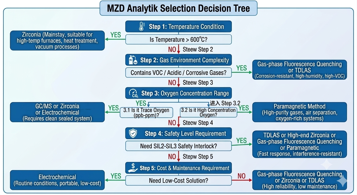
6.3 Step 3: Match Technical Technology (Condition → Technology Mapping)
Based on the engineering boundaries described in Chapter 5, the following cross‑industry mapping can be established:
Operating Condition | Recommended Technical Technology |
High temperature (>600°C) | |
VOC environments | |
High humidity / condensation risk | TDLAS / Gas‑phase fluorescence quenching |
Medium/low pressure / hydrogen | TDLAS |
Clean gases / high precision | |
ppb–ppm trace oxygen | GC / MS |
SIS interlocks | TDLAS |
Portable / cost‑sensitive |
This mapping framework applies across energy, chemical, semiconductor, combustion, and industrial‑gas sectors.
6.4 Selection Comparison and Decision Making
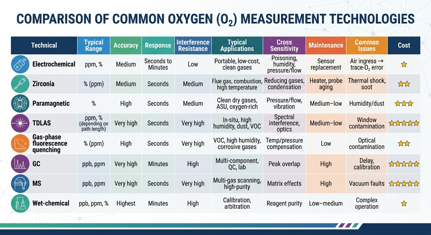
The following table summarizes practical selection criteria. Final decisions must consider the entire measurement loop, including analyzer, sampling installation, transmitter/logic unit, validation tests, and diagnostic systems—especially for safety‑related applications.
Oxygen‑analysis selection must be condition‑driven, not technology‑driven. The correct workflow is:
Define operating conditions → Determine measurement unit → Match technical technology
Each of the eight technical technologies has clear engineering boundaries. Only when system engineering and unit selection are correct can the technology perform as intended.
7. Engineering Implementation Guide:
From Analyzer to a Fully Realized Measurement System**
Engineering implementation of industrial oxygen analysis is not merely an equipment‑installation task. It is the process of integrating technical technology, system design, unit selection, pressure compensation, diagnostic capability, and condition compatibility into a measurement system that can operate stably over the long term.
Regardless of whether the technology is zirconia, TDLAS, gas‑phase fluorescence quenching, paramagnetic, or others, the quality of engineering implementation determines the final system performance.
7.1 Commissioning
The goal of commissioning is to ensure that the system operates stably under real operating conditions. Key steps include:
Sampling‑system sealing (helium leak test, pressure‑hold test)
Heat tracing and condensation control (dew point +15–20°C)
Stable pressure/flow control (regulation, limiting, monitoring)
Verification of unit selection and pressure‑compensation model
Establishing initial zero/span baselines
Defects during commissioning will later manifest as drift, slow response, or interlock failure.
7.2 Calibration
Calibration establishes the mapping between instrument output → oxygen partial pressure. Key considerations include:
Background‑gas matching: H₂ → H₂ calibration gas CO₂ → CO₂ calibration gas VOC → inert‑gas cylinders Air → air/N₂
Pressure‑compensation calibration: Pressurized systems must validate the compensation model.
Temperature calibration (zirconia): B‑type thermocouple reference must be verified.
Optical calibration: Window cleaning, optical alignment, attenuation check.
Calibration intervals:
Clean gases: 6–12 months
VOC / high humidity: 1–3 months
SIS: follow SIL procedures
7.3 Validation
Validation focuses on overall system performance, not just analyzer accuracy.
Key validation items:
T90 response time (SIS requires <2–5 s)
Stability under pressure fluctuations
Condensation‑risk assessment
Background‑gas variation effects
Interlock setpoint verification (SIL workflow)
7.4 Diagnostics
Long‑term stability depends on diagnostic capability, including:
Optical attenuation (TDLAS / fluorescence quenching)
Heater and temperature‑control loop (zirconia)
Electrode impedance (electrochemical)
Flow/pressure monitoring
High‑end platforms support predictive maintenance and automatic compensation.
7.5 Reliability and Lifetime Management
Key measures:
Keep sampling system dry and clean (condensation is the primary cause of failure)
Regularly verify pressure compensation and temperature control
Establish maintenance cycles: Electrochemical: 1–3 years Zirconia: 3–10 years Optical systems: periodic cleaning
Record trend data: Zero point, optical attenuation, temperature, pressure‑compensation deviation
Application Note: Industrial Oxygen Analysis Technologies and Application Selection Guide  , if you need more information, please contact us at sales@mzdd.de.
For product information, please visit:
Fluorescence quenching O2 analyzer