Application of SMART-MT trace moisture analyzer in chlorine turbine compressor system
Chlorine gas turbine compressors are widely used in the chlor-alkali industry. In order to prevent damaging corrosion of the compressor by wet chlorine gas, it is very important to monitor the moisture content of the chlorine gas entering the compressor and interlock protection of the compressor.
To on-line monitor whether the pre-cooler is leaking, many compressor users also use MZD SMART trace moisture analyzer to monitor the chlorine gas at the outlet of the compressor to avoid the delays in monitoring chloride ion measurements in cooling water with conductivity and pH/ORP measurements, to avoid serious losses from chlorine compressor leak accidents.
SMART-MT trace moisture analyzer principle
The sensor pillar is plated with parallel spiral platinum layer as the electrode, and the hydrated phosphorus pentoxide film is coated between the platinum layer. Phosphorus pentoxide has a strong water absorption, when chlorine gas flows steadily through the sensor flow cell, where the water is absorbed to generate phosphoric acid, the reaction formula is as follows:
P2O5 + 3H2O → 2H3PO4
At the same time, between the two platinum layers to plus DC voltage, that has the electrolysis reaction, phosphoric acid is reductively decomposed into oxygen,chlorine, phosphorus pentoxide.The reaction formula is as follows:
4H3PO4→6H2+3O2+2P2O5
It is known from Faraday's electrolysis law: the electricity required to electrolyze 1 mole equivalent of substance is 96,500 coulombs, which is also the electricity required to electrolyze 9.01 grams of water, thus it can be seen that the electrolytic current between the platinum wire electrodes is a linear function of the moisture content in the quantitative gas.
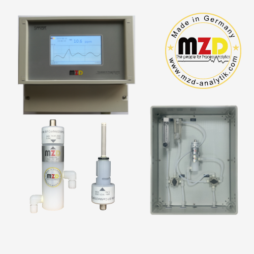
SMART-MT trace moisture analyzer Introduction
SMART-MT trace moisture analyzers are used to determine the moisture content in acidic and neutral gases. Measuring the moisture concentration is helpful to control the moisture in gases to ensure the quality of manufactured products. It has proven to be stable and reliable for long-term measurement of moisture content in acidic and neutral gases. Such as chlorine, hydrogen chloride, sulfur dioxide and other strong corrosive gases, air, nitrogen, oxygen, inert gases, carbon monoxide, cooling gases, acetylene and other light hydrocarbon gases in trace moisture. The analyzer performs well, rarely requires maintenance, and has an extremely long (sensor) life.
The factory calibrated range of the trace moisture analyzer is 0 to 2000ppm (sensitivity is 0.1PPM), and for the moisture content of chlorine is usually below 40ppm and the alarm value is 150ppm, 0~500ppm range is usually used.
The sensor has a double electrode of precious metal fixed on a cylindrical ceramic or glass, and the electrode is covered with phosphorus pentoxide coating. The sample gas flows from the bottom to the top of the flow cell at a flow rate of 20 NL/h or 100 NL/h, usually at a slight positive pressure (20-500 mbar). The new design of the flow cell body with movable pins guarantees a high sensitivity and enhanced handling capacity.
Installation
For safety reasons, flow cells made of PVDF corrosion-resistant material can withstand 3 Bar, above which the pressure must be passed through a pressure reducer. If the pressure difference is not sufficient to maintain the required gas flow in the system, an appropriate sample gas pump needs to be installed behind the measuring instrument. A constant flow rate regulated by a rotameter ensures reliable measurement results. Too high a flow rate will make the measurement result larger than the actual value, too low a flow rate will make the measurement result smaller than the actual value.
Make sure the length of the sampling inlet pipe is as short as possible. Plastic pipes must not be used as sampling pipes for moisture analyzers because they can cause moisture to diffuse into the gas. The airflow behind the measuring cell must not be under pressure and the exhaust pipe length must be at least 1 meter. Too short a length of exhaust pipe can cause the gas to diffuse into the surroundings.
The minimum length of the cable between the measuring cell and the analyzer unit is 1.5 m and the maximum length is 150 m. For the measurement of flammable and explosive gases, intrinsically safe explosion-proof sensors and Ex d analyzer unit should be used.
Instrument installation inspection and commissioning
Before starting the measurement, check the sample system for leaks and use N2 to purge it for inspection. If there is a leak, it is necessary to troubleshoot the leak. There must be no slight leaks that could lead to siphoning and lead to high measured values! Depending on the components of the device and the length of the exhaust pipe, this process can take several hours.
The process of obtaining stable measuring value may take several hours, or even more than 24 hours, it depends on the moisture in the process and the length of the sample gas inlet tube, because the water absorbed on the "inside surface" of the measuring tube and the flow cell must be blown off. If the displayed value does not change significantly within 30 minutes, the preparation is complete.
Instrument Maintenance
If the sample gas is not available, be sure to switch the 3-way valve to use nitrogen or instrument air to protect the moisture analyzer. If nitrogen or instrument air is also not available, be sure to switch the 4-way valve so that the inlet and outlet of the sensor are not in circulation.
Before regenerating/coating the sensor, be sure to switch the 3-way valve and use nitrogen or instrument air to purge the sensor for 3 to 10 minutes, then switch the four-way valve so that the air inlet and outlet of the sensor do not circulate, then gently pull the sensor out.
Routine maintenance procedures and sensor regeneration
1. daily inspection of the controller for normal operating status.
2. daily inspection of the sampling unit for leaks and corrosion conditions.
3. daily inspection for stable flowmeter readings.
4. the sensor needs to be regenerated regularly every three months or when the measured value is less than 0.3ppm.
5. the following materials need to be prepared before regeneration/coating: laboratory distilled water (or ultra-pure water), laboratory filter paper, acetone, and 40% phosphoric acid solution.
6. Before regenerating/coating the sensor, remove the instrument interlock signal, switch the 3-way valve first, use nitrogen/instrument air to purge for 3~10 minutes, then switch the 4-way valve so that the inlet and outlet of the sensor are not in circulation, disconnect the sensor cable and gently lift out the sensor.
7. Rinse with water(recommend distilled water), wipe clean gently with soft laboratory filter paper, and then rinse/dry repeatedly until there are no black/yellow stains on the filter paper and the sensor surface is clean. After drying with filter paper, then dry with acetone and wait for 1~2 minutes, and then wipe clean with filter paper again. (Using acetone to dry the sensor is not necessary to ceramic sensor). Plug in the sensor cable and confirm the zero point.
8. If the analyzer unit shows that the cleaning is not clean, repeat the distilled water cleaning/filter paper drying/acetone drying/filter paper drying steps repeatedly.
9. If the display shows cleaning is complete, begin coating by applying a thin, even layer of 40% phosphoric acid solution to the sensor, then a lot of small air bubbles will be seen on the surface of the sensor. Insert the sensor back into the flow cell and click "ok" on the controller and return to the main measurement menu.
10. After the sensor regeneration/coating, first purge with nitrogen 5~30 minutes, observe the change of measurement value. If the measured value drops and stabilizes after 5~30 minutes, it can be judged that the sensor regeneration/coating is completed, can switch 3-wavle to let the sample gas through the measuring cell, and the analyzer can be put into normal measuring status.
11. After the instrument value is stable, put the measured value back into the interlock.
Checking steps for problems
1. Check whether the power supply is normal (100~230VAC/50HZ, 24VDC, see the label of the analyzer).
2. Check whether the sample gas flow is stable, because strong flow fluctuations can cause measurement errors.
3. Switch the three-way valve to nitrogen or instrument air and observe whether the measured value changes, the speed of change and the size of the change.
4. Due to the presence of dust in the sample gas or gas reaction on the sensor to form phosphate compounds, or they directly covered the sensor to form a "protective layer", for example, oil and dust and other mechanical impurities, these will have an impact on the electrolysis, affecting the measurement, resulting in measurement errors. The sensor needs to be cleaned, regenerated and recoated.
Summary
Trace moisture analyzer is installed in the compressor first outlet and the last outlet, after long-term operation proved that the instrument has the characteristics of fast analysis, high precision, strong stability, etc., which solves the problem of artificial analysis is not timely, error or even can not be analyzed, very conducive to the timely adjustment of the process situation, stable production, and achieved satisfactory results. It is necessary to pay attention to the training of instrument operation and maintenance personnel, as well as the regular maintenance and the sensor regeneration.